Wednesday, May 6, 2009

Testing Data with our product

Test our unipolar stepper motor in flat surface


Testing the unipolar stepper motor in slow speed


Testing the stepper motor in medium speed


Testing the unipolar stepper motor in full speed

From the 3 testing data carried out, we will be able to form a formula for the speed in flat surface but the accurancy is quite low.

Summary of the testing result

Final Report of the product

Final Report of product

Tuesday, May 5, 2009

Final Product

Final circuit diagram
In the project design, two microcontrollers modeled PIC16F877A are used. Cascade microcontroller mechanism used in the design. Microcontroller 1 located at the racing car and microcontroller 2 embedded in user’s remote controller. The speed of the stepper motor detected by microcontroller 1 and the speed calculated referring to the speed equation obtained. The speed information is sent to the microcontroller 2 via cascade PIC. Microcontroller 2 receives the signal and displays the speed in the LCD screen. At the user’s remote controller, there is motor speed control mechanism. The speed controlled by potentiometer. Large value resistance will produce low speed while small value resistance produces high speed. The speed control information will send from the potentiometer to microcontroller 2. Microcontroller 2 detects the speed and sends the data to microcontroller 1. Speed of the stepper motor will be controlled by microcontroller 1. The speed control mechanism functions as the test board of the stepper motor. Basically, there is not much circuitry in our design. Main part in our design is the PIC programming. Most of the mechanisms are controlled by the PIC. There is also, motor driver to drive the stepper motor. The motor driver used is, SD02B from Cytron Technology. In the motor driver itself, contain a PIC. This PIC is used to control the UART (Universal Asynchronous Receiver Transmitter). UART is a piece of hardware that translates data between parallel and serial forms. Both cars contain the same circuitry mechanism and both unipolar and bipolar motor are using the same motor driver. PCB board was used to design the circuit. The racing car and remote controller is connected by 3m length of wires.

Our final product
The first version of our educational kit for stepper motor only can move forward and backward because we are using one stepper motor due budget limiting. The video above shown that the stepper motor has high torque when at low speed. This is one of the advantage of stepper motor.

Application Notes 5 : LCD Screen

lcd(nabilah)

Application Notes 3 : Motor Driver of stepper motor

Motor Driver of Stepper Motor

Application Notes 2 : RF (transmitter and Receiver)

Application Notes RF (transmitter and Receiver)

Application Notes 1 : Speed Control for Stepper Motor

Application Notes 1

Monday, May 4, 2009

Hardware Development and Prototype

After we purchased the unipolar stepper motor, the school provide us again one bipolar stepper motor. As a result we decided to compare the performance between the unipolar stepper motor and bipolar stepper motor.

Construction of the racing cars body is by using aluminum and plastics. There are only three tyres to each of the design. One tyre is controlled by the stepper motor and the others for balancing the car. Racing car using the unipolar stepper motor constructed using plastics. The basement of the car was obtained from ordinary toy car. We implemented the readymade basement to our design by doing some modification. Circuitry of the design was placed on top the basement. The dimension of the car is 25cm in length and 10cm in width. Height of the car model is 6cm, without the circuit install in the car design.

Body of the bipolar racing car was build by using aluminium. It is constructed by hand. Same concept as the unipolar motor, there are only three tyres in the design and the circuit was placed on top of the basement. The car model gain power from battery source. The length of the model is 20cm and width is 10cm. Height of the car model is 18cm.

Structure of car control using unipolar stepper motor

Structure of a car control using bipolar stepper motor

The casing of remote control consists 3 push buttons (forward, backward and reset), one potential meter (adjust speed) and one toggol switch (on and off).

Casing of remote control

Problem Encountered

In the combining everthing that we discussed in previous posts, there are some features was modified or eliminated as we encountered some problems. There are two features that we modified which are radio frequency module (RF) and encoder.

The radio frequency signal is totally eliminated from our design. We are using wire cables instead of wireless. The reasons we eliminate the feature is the signal in the RF is interphasing with the other group frequency. Most of the other groups are using the same model of RF with the same frequency (433MHz). Distortion of information produced and consequently the data received or transmitted is not the acquired signal. In the design, the functionality of RF is very important. If the RF is not working properly, the design will become a big failure. Another reasons we give up for RF is protocol. The pre-set method to transmitter and receiver cannot applied in the our control car because the value of speed changing time by time. Therefore, the probability the receiver receive the wrong data is very high. As we discussed among the team members, we are not willing to take any risk, so we change the RF to the wire cables. Furthermore, the main purpose of the project is to build test board to stepper motor.

The second feature that we modified is the encoder, speed calculation. As we proposed, the encoder should detect the speed of the stepper motor. Unfortunately, the encoder that we are using was broke during the installation part. Because of time limiting factor, we modified the calculation speed mechanism. Microcontroller itself calculates the rotation of the stepper motor. Data collected from the test done in lab to come out with speed and torque equation. This equation is programmed in the microcontroller. Referring to this equation, the speed calculated.

Technical part 3.0 : Motor Driver of stepper motor

Motor Driver of stepper motor, SD02B

SD02B is designed to drive unipolar or bipolar stepper motor. The board incorporates most of the components of the typical applications. With minimum interface, the board is ready to Plug and Play. Simply add in power and a few push buttons, this driver is ready to drive unipolar or bipolar stepper motor. SD02B will actually drive stepper motor in bipolar method. However, since unipolar stepper motor can also be used as bi-polar stepper motor, thus this driver can be used to drive both unipolar and bipolar stepper motor. This stepper motor driver has been designed with capabilities and features of:

• Now comes with UART interface for easier communication between the user’s circuit and SD02B. By using the new UART control, user can

-On/Off, Run/Brake and change motor’s rotation direction
-Set motor speed
-Request for encoder value
-Track an encoder value and brake the motor
-Set new baud rate for the driver

• Support up to 2A per phase
• Smoother stepper motor rotation with 2/5/10 micro-stepping feature
• Able to drive stepper motor from 3V to 40V.
• 8V to 24V compatible for driver circuit supply voltage
• 5V logic level compatible inputs.
• Maximum speed up to 1000 steps per second or 1KHz pulses
• Enable/Disable pin for low power consumption mode.
• Heat sink with fan for fast thermal release

Circuit diagram of motor driver and stepper motor

Technical 2.4 : (transmitter and receiver)

A experiment is carried out at robocon lab, sktm, ums to test the efficiency of RF (transmitter and receiver). From the analysis above, the result can be concluded when the distance starts to increase the efficiency start to decrease. From 15 m to 19 m, the data receive start to corrupted by surrounding and after 20 m the radio frequency is out of the function.

Technical 2.3 : RF (transmitter and receiver)

Theory and Setting of Asyncronous Mode of USART of Receiver


Circuit diagram of receiver
The 8 led inside the circuit diagram is to make sure that the data receive from transmitter are correct data.
RCSTA is the receive control register for the microcontroller. This register has to be initializing correctly in order to make the receiver work. By referring to the data sheet, the RCSTA is initialized as B'10010000' which mean that it continuously receive 8 bit data, asynchronous mode. The SPEN Flag bit in RCSTA have to be set to enable the serial port. The baud rate for the receiver has to be the same with the transmitter.
Each bit in RCSTA register
When receiving data from the transmitter, the data is first stall in Receive Shift Register (RSR). After that the received data is transferred to the RCREG register when it is empty. Once the transferring process from the RSR to RCREG is complete, the flag bit RCIF will be set. The RCREG is a double-buffered register which mean that it can store two byte of data. When the 2nd data come in but the 1st data have not been read yet, the data will store in the second slot of the RCREG. When the 1st data is read, the 2nd data will move to the 1st slot and new data can be move into RCREG. However, when the RCREG is full and the 3rd data is store in the RSR, the flag bit OERR will be set and the data in RSR will lost. In addition, all the receive process will be stop. Hence it is a must to clear the flag bit OERR in order to retrieve the receiving process. Flag bit OERR can be clear by first clear the CREN and then set it again. Figure 1.8 shows how the overrun error being detected and how it is solve.


Programming of receiver

Circuit diagram on breadboard

Technical 2.1 : RF (transmitter and receiver)

Interface RF - Module with microcontroller
MPLAB is used as the programming software and c language is used as the programming language. To interface RF module with microcontroller, Universal Synchronous and Asynchronous Receiver and Transmitter (USART) or also known as Serial Communications Interface is used. USART is used for transmit and receive serial data. The operation of USART can be divided into two types which is synchronous and asynchronous. Synchronous mode uses a clock and data line. Asynchronous mode does not use clock accompanying the data. Asynchronous mode will be use in interfacing the RF module with the microcontroller. Table below show the register and flag bit that will be used together with its description.

Sunday, May 3, 2009

Technical 2.2 : RF (transmitter and receiver)

A) Transmitter
Theory and Setting Asynchronous Mode of USART for Transmitter

Circuit diagram for transmitter

In previous post, it is shown that the data pin of the transmitter module is connected to the TX pin of the microcontroller. Seem TX pin normally used as a digital I/O port, to enable the TX port as a serial port, SPEN which is bit 7 in RCSTA have to be set. Bit six in TRISC of PIC16F877A have to be clear in order to make the TX pin as an output pin. TXSTA is the transmit control register for the microcontroller. This register has to be initializing correctly in order to make the transmission work. By referring to the data sheet, the TXSTA is initialized as B'00100000' which mean that it transmit 8bit data in asynchronous low speed mode.


Representation of each bit in TXSTA Register

Next is to set the baud rate of the transmitter. Baud rate refers to the speed at which the serial data is transferred, in bits per second. In Asynchronous mode, the baud rate generator sets the baud rate using the value in the SPBRG register. The BRGH bit in TXSTA selects between high and low speed options for greater flexibility in setting the baud rate. From the initialization of TXSTA shown above, the BRGH is clear which mean that the baud rate is in low speed and the SPBRG register is set to 129 where the rate is 2.4K bit per second. The Baud rate for both transmitter and receiver must be the same in order for the data transmitted to receive in the receiver. The baud rate can be calculated with the formula shown below.

12Desired baud rate= Fosc64/(x+1)/Where, Fosc = frequency of crystal used

X= value that will be set in the SPBRG register

Example:
Taking the desired baud rate = 2.4K
2.4K=20M/64(x+1)
x=129

When a 1 byte digital data is being transmitted, it is transmit from the less significant bit to the most significant bit. This means that the transmitter transmits digital data bit by bit to the receiver.
The signal is high when no transmission (or reception) is in progress and goes low when the transmission starts. The receiving device uses this low-going transition to determine the timing for the bits that follow. The signal stays low for the duration of the START bit, and is followed by the data bits, Least Significant bit first. The USART can transmit and receive either eight or nine data bits. The STOP bit follows the last data bit and is always high. The transmission therefore ends with the pin high. After the STOP bit has completed, the START bit of the next transmission can occur.


Setup for transmitter

During transmitting data, the heart of the transmitter is the Transmit Shift Register (TSR). This register obtain the data from the transmit buffer, TXREG. Hence, to transmit a data to the receiver, first is to move the desire transmit data to the TXREG then it will load to TSR to be transmitted. To check whether the data in TXREG had been move to TSR, the flag bit TXIF which located in the PIR1 is checked. If TXREG is empty (means the data already load to TSR) the flag bit TXIF will be set. Hence new data can be load to TXREG to be transmitted next. The Bit TXEN in TXSTA 6 is always set so that all the data in TSR will be transmit.

The transmitter’s program runs

Programming for transmitter


Circuit diagram on breadboard

Technical Part 1 : Speed Control

Circuit diagram of voltage regulator, 7805
Due to the input valtage to PIC 16F 877A must be 5 V, therefore a voltage regulator 7805 is used to convert the 12 V power supply to 5 V and supply the voltage to the PIC 16F 877A. From circuit above the two capacitors 100uF are connected with 12V - ground and 5 V - ground, they are used to stabilised the voltage from power supply. However, the real theory to calculte the value of capicators should be used still in process. A diode-Led is used in the circuit above to indicate the 12 V sucessfully converted to 5 V when the Led is light on. The 5-v voltage cannot be supply directly to LED, it will damage the LED. So a resistor 330 ohm is used to drop the voltage and it can be calculated by ohm law.
Circuit diagram for speed control

PIC16F 877A
First , the PIC 16F 877A will be discussed. To activate PIC 16F 877A, 7 pin must be compulsory to be connected. Pin 1 which is master clear, a 4.7 K ohm which is as a pull out resistor. However the value of the pull out resistor chosen depend on the input impedance of microcontroller. We still on the process to find out the calculation for this. Pin 11, pin 32 are connected to 5 V supply and pin 12, pin 31 are connected to ground. Next, pin 13 and pin 14 must connect to an oscillator. The function of oscillator is giving the clock to microcontroller. We chose 20MHz oscillator for PIC16F877A. However, if your design does not need the so fast speed, you can use lower value of oscillator. It will help you to save the power. We still find how to calculate this.

Speed control
Due to microcontroller work in analogoues 0 and 5 V. It is impossible to use that for speed control. The better way is used the digital method to control the speed for stepper motor. As a result the first thing we need to do is change the analogoues to digital of microcontroller. To varied the digital value, a potential meter is needed which connected in pin2 as shown at circuit diagram above. The 8 led at pin 33 to pin 40 is a testing method to let us know the digital value after we adjust the potential meter.

Setup for ADC


Programming for speed control

Job distribution

Our project design is most of part in writing programming and hardware constructing. So we want to make sure every of our team members know how to write te programming. So we divide the job one part by one part to our team and give everybody a chance to learn the programming. Job distribution as shown below :

Wong Jih Kian : Speed control
Goai Teck Liang: Radio Frequency
Faizal: Motor Driver
Tamil : Encoder
Nabilah : LCD screen

After our team member knows how to write the programming for their own parts, we will combine everything together.

Things that we purchsed

Due to lack experience in microcontroller, and newbie in project design. Most of the devices we buy from shops rather to construst and build. We are mainly focusing on writing programming and learn how maximase to use those devices we buy.

Unipolar Steppr motor


Photo above shows a unipolar stepper motor that my team will use it. It is bought from cytron tecnology and cost us RM 50. We chose unipolar stepper motor for our project design because it is more easy to use it compare to bipolar stepper motor.

Motor Driver

Due to lack experience in designing the motor driver of stepper motor, we plan to buy this motor driver from cyton tecknolgy. We will discuss in details and advantages in future post. The motor driver cost us RM 135.

Encoder

Photo above shown an encoder. We are quite regret to buy this encoder. This is because we can easily build my our own. Furthermore, this encoder didnt provide the output shaft for us. So it make difficulty for us to construct a output shaft for it. It is very expensive , RM 60.

Radio Frequency (transmitters and receivers)


Photo above shows 2 set of different frequencies of radio frequency, 315 MHz and 415MHz. Due to we want to communicate in bi-directional between car and remote control that we already discussed in previous post. Therefore, 2 set of transmitters and receivers are needed.

Microcontroller (PIC 18 F 877A)
Photo above shows the 40 pin microcontroller that provided by the school. We need to learn it start from zero.

LCD display
Photo above shows the LCD display that we purchase from cytron. It is a cheaper LCD display. Again we need to learn how to write the programning for this LCD display. We will use this LCD screen to display the speed as well as the torque for stepper motor.

Saturday, May 2, 2009

Estimated budget for our product

Budgets are difficult but essential tools for project management. They permit teams to identify the financial and other resources required, and to match those requirements to the available resources. Budgets also require teams to account for project monies. Finally, budgets serve to formalize the support of the larger organization from which is drawn. Design project budgets normally include research expenses, materials for prototypes and support expenses related to the project. The table below is showing our estimated budgets:

Please click the photo to enlarge it
Estimated budget

Technical Gannt Chart for our team

To start any project, the technical gannt chart is very important to the team. It can push us to do for project and it is more systematically to the design. The photo below is shown the technical gannt chart designed by the Touch The Sky.

Please click the photo to enlarge it

Research method on our product

The development of the mass capacitive sensor involves research, step by step. The steps are affected by other factors, which cause some delay in certain cases. Each of the steps was planned well before proceed and sometimes interfere between each another occurred due to speed up the process especially in the cases where delay happened. Table 1 shows the overall flow of the project. The steps involved are elaborated briefly:
Please click the photo below to enlarge it

Table 1 : Flowchart of the project
Literature review and study are the ways for understanding of the title of the project. Research has been carried out on the papers, journals, books and Internet resources to create a strong background on the related topics involved in the project. The research conducted about the definition of stepper motor, microcontroller technology, stepper motor types (bipolar and unipolar specifically), motor performance characteristics, and the application of the stepper motor. This step also involved the complete understanding of the general view of the project’s scope.

Fast Diagram of our product

In the previous post, we already discuss the executive summary of our product. By seeing the fast diagram below, you will more understand about our product as well.


Please click the photo to enlarge it

Executive Summary of Our Project Design

Our product is Test Board for Stepper Motor. The main purpose of designing this product is for educational kit for a university student. However to make the learning process more interesting, we design the test board for the stepper motor in the form of car control. The main component of this product is stepper motor, PIC microcontroller, encoder and LCD (liquid crystal display). Moreover to control the car control we are using wireless remote by radio frequency.
The car is built with three wheels. For this product we only used one stepper motor and it only control one wheel of the car and the other two wheels is used to stabilize the car. It means that our car only can run forward and backward. Since our purpose of design this project is for educational kit, we ignore the car control problems to turn left or right.
In technically, we are design circuit by referring to the books, internet and also by our own idea. Then we are using Proteus 7 professional to design the complete circuit. Moreover to interface PIC with the stepper motor and LCD, we are using C programming. The complete program is simulated in the MPLAB IDE v8.10 and it is transfer to the PIC using PICkit V2.55 program.
There are many experiments we are doing in a process of building this product. We are dividing our product into several technical parts such as encoder, LCD, speed control, remote control and also radio frequency. Each of the part is experimented separately and any changing will be done due to the time.
The stepper motor will be control by a remote control using radio frequency. The input will be send directly to the microcontroller and microcontroller will send the data to the motor drive. Therefore the motor drive will drive the motor. The output of the motor will be send to the encoder to calculate the speed and from the encoder, the speed will display to the LCD to display the output.

Friday, March 20, 2009

Microstepping theory of stepper motor

A bipolar stepper motor has two windings. The current through each winding is varied in order to rotate the stepper motor. When considering stepper motor drive techniques, a "phase diagram" is a useful visualization tool. The current through one winding Ia is plotted against the current through the other winding Ib. Modes of operation such as full stepping, half stepping, microstepping, and operation at different current limits can be easily visualized on such a diagram. In addition, it is possible to visualize changes in both power consumption and torque as a function of angular position.

Simple stepper motor controllers are only capable of driving a winding with full positive current, no current, or full negative current. Given these available outputs it is only possible to implement full stepping, half stepping, or wave stepping.
Full Wave Stepping
In full stepping operation, the current required in each winding is either -Imax or +Imax. A step sequence of 4 full steps makes up one complete step cycle. Note that these full step positions are the same as the odd numbered positions from the half stepping sequence.
Phase diagram

Timing Diagram

Half-stepping
In a half stepping operation, the current required in each winding is either -Imax, 0, or +Imax. A step sequence of 8 half steps makes up one complete step cycle.
Phase diagram
Timing diagram
Wave Stepping Wave stepping is another method of full stepping, but with reduced power requirements (and corresponding torque output) since only one winding is powered at a time. The current required in each winding is either -Imax, 0 or +Imax. A step sequence of 4 full steps makes up one complete step cycle. Note that these full step positions are the same as the even numbered positions from the half stepping sequence.

Phase diagram

Timing diagram
Microstepping - square path
This method of microstepping provides the highest peak torque if you are limited by available supply voltage.

Phase diagram
Timing diagram
Microstepping - circular path
This method is also referred to as sine cosine microstepping and is usually what people are referring to when they talk about microstepping, though in fact it is only one method.
Phase diagram
Timing diagram

Bipolar Stepper Motor

Bipolar motors have logically a single winding per phase. The current in a winding needs to be reversed in order to reverse a magnetic pole, so the driving circuit must be more complicated, typically with an H-bridge arrangement. There are two leads per phase, none are common.
Static friction effects using an H-bridge have been observed with certain drive topologies. Because windings are better utilised, they are more powerful than a unipolar motor of the same weight.

Structure of an H-Bridge (highlighted in red)

An H-bridge is an electronic circuit which enables a voltage to be applied across a load in either direction. These circuits are often used in robotics and other applications to allow DC motors to run forwards and backwards. H-bridges are available as integrated circuits, or can be built from discrete components.


A "double pole double throw" relay can generally achieve the same electrical functionality as an H-bridge (considering the usual function of the device). Though an H-bridge would be preferable where a smaller physical size is needed, high speed switching, low driving voltage, or where the wearing out of mechanical parts is undesirable.


The term "H-bridge" is derived from the typical graphical representation of such a circuit. An H-bridge is built with four switches (solid-state or mechanical). When the switches S1 and S4 (according to the first figure) are closed (and S2 and S3 are open) a positive voltage will be applied across the motor. By opening S1 and S4 switches and closing S2 and S3 switches, this voltage is reversed, allowing reverse operation of the motor.


Using the nomenclature above, the switches S1 and S2 should never be closed at the same time, as this would cause a short circuit on the input voltage source. The same applies to the switches S3 and S4. This condition is known as shoot-through.

Unipolar Stepper Motor

Photo above shows a connection of a unipolar stepper motor

Unipolar stepper motor has logically two windings per phase, one for each direction of current. Since in this arrangement a magnetic pole can be reversed without switching the direction of current, the commutation circuit can be made very simple (eg. a single transistor) for each winding. Typically, given a phase, one end of each winding is made common: giving three leads per phase and six leads for a typical two phase motor. Often, these two phase commons are internally joined, so the motor has only five leads.

A microcontroller or stepper motor controller can be used to activate the drive transistors in the right order, and this ease of operation makes unipolar motors popular with hobbyists; they are probably the cheapest way to get precise angular movements.

(For the experimenter, one way to distinguish common wire from a coil-end wire is by measuring the resistance. Resistance between common wire and coil-end wire is always half of what it is between coil-end and coil-end wires. This is due to the fact that there is actually twice the length of coil between the ends and only half from center (common wire) to the end.).A quick way to determine if the stepper motor is working is to short circuit every two pairs and try turning the shaft, whenever a higher than normal resistance is felt, it indicates that the circuit to the particular winding is closed and that the phase is working.Unipolar stepper motors with six or eight wires may be driven using bipolar drivers by leaving the phase commons disconnected, and driving the two windings of each phase together[diagram needed]. It is also possible to use a bipolar driver to drive only one winding of each phase, leaving half of the windings unused[diagram needed].

Thursday, March 19, 2009

What is Stepper motor?

A stepper motor (or step motor) is a brushless, synchronous electric motor that can divide a full rotation into a large number of steps. The motor's position can be controlled precisely, without any feedback mechanism (see open loop control). Stepper motors are similar to switched reluctance motors (which are very large stepping motors with a reduced pole count, and generally are closed-loop commutated.)

Theory of Stepper motor

The top electromagnet (1) is turned on, attracting the nearest teeth of a gear-shaped iron rotor. With the teeth aligned to electromagnet 1, they will be slightly offset from electromagnet
The top electromagnet (1) is turned off, and the right electromagnet (2) is energized, pulling the nearest teeth slightly to the right. This results in a rotation of 3.6° in this example


The bottom electromagnet (3) is energized; another 3.6° rotation occurs.


The left electromagnet (4) is enabled, rotating again by 3.6°. When the top electromagnet (1) is again enabled, the teeth in the sprocket will have rotated by one tooth position; since there are 25 teeth, it will take 100 steps to make a full rotation in this example.

Objective of the project Design

OBJECTIVE
Design a test board for stepper motor. A product uses the test board should be designed. In addition, the product should be marketable and would appeal to the public.


Indented Objectives List
1. The product must be display the speed in the LCD screen
1.1 The product must be able to display the speed measured on a screen.
1.2 The product must be sensitive to small variations in speed of the user.
1.3 The speed sensors used must be reliable.


2. The product should be marketable
2.1 The product must be interesting
2.1.1 The product should be inexpensive to produce
2.2 The product must be attracting
2.2.1 The product should be suitable to all generation and worldwide.
2.3 The product must be convenient
2.3.1 The product must have simple structure
2.3.2 The product must be easy to operate
2.4 The product must be safe

2.4.1 The product must be well-insulated

Client Requirement From Our Project

In this project design, the client requires us to do a test board for the stepper motor. Inside the test board, microcontroller should be used to control the speed of the stepper motor. A microcontroller is a single integrated circuit with central processing unit (ranging from small and simple 4-bit processors to complex 32- or 64-bit processors). It contains the serial input/output such as serial ports (UARTs). It has the peripherals such as timers, event counters, PWM generators, and watchdog . In addition, microcontroller has volatile memory (RAM) for data storage and clock generator which often an oscillator for a quartz timing crystal, resonator or RC circuit . It includes analog-to-digital converters.. It requires in-circuit programming and debugging support.


Photo above shows a example of a microcontroller
In every stepper motor, it must have a pulse to generate the stepper motor. As a result the client requires us to build the pulse generator to the stepper motor. Pulse generators can either be internal circuits or pieces of electronic test equipment used to generate pulses.

Beside that, the client requires us to have a motor driver to drive the stepper motor. Stepper motor performance is strongly dependent on the drive circuit. Torque curves may be extended to greater speeds if the stator poles can be reversed more quickly, the limiting factor being the winding inductance. To overcome the inductance and switch the windings quickly, one must increase the drive voltage. This leads further to the necessity of limiting the current that these high voltages may otherwise induce.


Photo above shows a example of a stepper motor

Photo above shows a example of a motor driver of a stepper motor
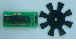
Inside the test board, it must contain the encoder to calculate the speed of stepper motor and display it at LCD display. An encoder is a device used to change a signal (such as a bitstream) or data into a code. The code may serve any of a number of purposes such as compressing information for transmission or storage, encrypting or adding redundancies to the input code, or translating from one code to another. This is usually done by means of a programmed algorithm, especially if any part is digital, while most analog encoding is done with analog circuitry.

Photo above shows a example of a encoder
After calculate the speed of the stepper motor, the value of the speed should be displayed in LCD screen in the test board of the stepper motor.

Photo above shows a example of a LCD Screen

We combine all the client‘s requirement for the test board for stepper motor, the test board should have a pulse generator to generate the pulse, motor driver to drive the stepper motor, encoder to calculate the speed and LCD screen to display the speed of stepper motor.