Friday, March 20, 2009

Microstepping theory of stepper motor

A bipolar stepper motor has two windings. The current through each winding is varied in order to rotate the stepper motor. When considering stepper motor drive techniques, a "phase diagram" is a useful visualization tool. The current through one winding Ia is plotted against the current through the other winding Ib. Modes of operation such as full stepping, half stepping, microstepping, and operation at different current limits can be easily visualized on such a diagram. In addition, it is possible to visualize changes in both power consumption and torque as a function of angular position.

Simple stepper motor controllers are only capable of driving a winding with full positive current, no current, or full negative current. Given these available outputs it is only possible to implement full stepping, half stepping, or wave stepping.
Full Wave Stepping
In full stepping operation, the current required in each winding is either -Imax or +Imax. A step sequence of 4 full steps makes up one complete step cycle. Note that these full step positions are the same as the odd numbered positions from the half stepping sequence.
Phase diagram

Timing Diagram

Half-stepping
In a half stepping operation, the current required in each winding is either -Imax, 0, or +Imax. A step sequence of 8 half steps makes up one complete step cycle.
Phase diagram
Timing diagram
Wave Stepping Wave stepping is another method of full stepping, but with reduced power requirements (and corresponding torque output) since only one winding is powered at a time. The current required in each winding is either -Imax, 0 or +Imax. A step sequence of 4 full steps makes up one complete step cycle. Note that these full step positions are the same as the even numbered positions from the half stepping sequence.

Phase diagram

Timing diagram
Microstepping - square path
This method of microstepping provides the highest peak torque if you are limited by available supply voltage.

Phase diagram
Timing diagram
Microstepping - circular path
This method is also referred to as sine cosine microstepping and is usually what people are referring to when they talk about microstepping, though in fact it is only one method.
Phase diagram
Timing diagram

Bipolar Stepper Motor

Bipolar motors have logically a single winding per phase. The current in a winding needs to be reversed in order to reverse a magnetic pole, so the driving circuit must be more complicated, typically with an H-bridge arrangement. There are two leads per phase, none are common.
Static friction effects using an H-bridge have been observed with certain drive topologies. Because windings are better utilised, they are more powerful than a unipolar motor of the same weight.

Structure of an H-Bridge (highlighted in red)

An H-bridge is an electronic circuit which enables a voltage to be applied across a load in either direction. These circuits are often used in robotics and other applications to allow DC motors to run forwards and backwards. H-bridges are available as integrated circuits, or can be built from discrete components.


A "double pole double throw" relay can generally achieve the same electrical functionality as an H-bridge (considering the usual function of the device). Though an H-bridge would be preferable where a smaller physical size is needed, high speed switching, low driving voltage, or where the wearing out of mechanical parts is undesirable.


The term "H-bridge" is derived from the typical graphical representation of such a circuit. An H-bridge is built with four switches (solid-state or mechanical). When the switches S1 and S4 (according to the first figure) are closed (and S2 and S3 are open) a positive voltage will be applied across the motor. By opening S1 and S4 switches and closing S2 and S3 switches, this voltage is reversed, allowing reverse operation of the motor.


Using the nomenclature above, the switches S1 and S2 should never be closed at the same time, as this would cause a short circuit on the input voltage source. The same applies to the switches S3 and S4. This condition is known as shoot-through.

Unipolar Stepper Motor

Photo above shows a connection of a unipolar stepper motor

Unipolar stepper motor has logically two windings per phase, one for each direction of current. Since in this arrangement a magnetic pole can be reversed without switching the direction of current, the commutation circuit can be made very simple (eg. a single transistor) for each winding. Typically, given a phase, one end of each winding is made common: giving three leads per phase and six leads for a typical two phase motor. Often, these two phase commons are internally joined, so the motor has only five leads.

A microcontroller or stepper motor controller can be used to activate the drive transistors in the right order, and this ease of operation makes unipolar motors popular with hobbyists; they are probably the cheapest way to get precise angular movements.

(For the experimenter, one way to distinguish common wire from a coil-end wire is by measuring the resistance. Resistance between common wire and coil-end wire is always half of what it is between coil-end and coil-end wires. This is due to the fact that there is actually twice the length of coil between the ends and only half from center (common wire) to the end.).A quick way to determine if the stepper motor is working is to short circuit every two pairs and try turning the shaft, whenever a higher than normal resistance is felt, it indicates that the circuit to the particular winding is closed and that the phase is working.Unipolar stepper motors with six or eight wires may be driven using bipolar drivers by leaving the phase commons disconnected, and driving the two windings of each phase together[diagram needed]. It is also possible to use a bipolar driver to drive only one winding of each phase, leaving half of the windings unused[diagram needed].

Thursday, March 19, 2009

What is Stepper motor?

A stepper motor (or step motor) is a brushless, synchronous electric motor that can divide a full rotation into a large number of steps. The motor's position can be controlled precisely, without any feedback mechanism (see open loop control). Stepper motors are similar to switched reluctance motors (which are very large stepping motors with a reduced pole count, and generally are closed-loop commutated.)

Theory of Stepper motor

The top electromagnet (1) is turned on, attracting the nearest teeth of a gear-shaped iron rotor. With the teeth aligned to electromagnet 1, they will be slightly offset from electromagnet
The top electromagnet (1) is turned off, and the right electromagnet (2) is energized, pulling the nearest teeth slightly to the right. This results in a rotation of 3.6° in this example


The bottom electromagnet (3) is energized; another 3.6° rotation occurs.


The left electromagnet (4) is enabled, rotating again by 3.6°. When the top electromagnet (1) is again enabled, the teeth in the sprocket will have rotated by one tooth position; since there are 25 teeth, it will take 100 steps to make a full rotation in this example.

Objective of the project Design

OBJECTIVE
Design a test board for stepper motor. A product uses the test board should be designed. In addition, the product should be marketable and would appeal to the public.


Indented Objectives List
1. The product must be display the speed in the LCD screen
1.1 The product must be able to display the speed measured on a screen.
1.2 The product must be sensitive to small variations in speed of the user.
1.3 The speed sensors used must be reliable.


2. The product should be marketable
2.1 The product must be interesting
2.1.1 The product should be inexpensive to produce
2.2 The product must be attracting
2.2.1 The product should be suitable to all generation and worldwide.
2.3 The product must be convenient
2.3.1 The product must have simple structure
2.3.2 The product must be easy to operate
2.4 The product must be safe

2.4.1 The product must be well-insulated

Client Requirement From Our Project

In this project design, the client requires us to do a test board for the stepper motor. Inside the test board, microcontroller should be used to control the speed of the stepper motor. A microcontroller is a single integrated circuit with central processing unit (ranging from small and simple 4-bit processors to complex 32- or 64-bit processors). It contains the serial input/output such as serial ports (UARTs). It has the peripherals such as timers, event counters, PWM generators, and watchdog . In addition, microcontroller has volatile memory (RAM) for data storage and clock generator which often an oscillator for a quartz timing crystal, resonator or RC circuit . It includes analog-to-digital converters.. It requires in-circuit programming and debugging support.


Photo above shows a example of a microcontroller
In every stepper motor, it must have a pulse to generate the stepper motor. As a result the client requires us to build the pulse generator to the stepper motor. Pulse generators can either be internal circuits or pieces of electronic test equipment used to generate pulses.

Beside that, the client requires us to have a motor driver to drive the stepper motor. Stepper motor performance is strongly dependent on the drive circuit. Torque curves may be extended to greater speeds if the stator poles can be reversed more quickly, the limiting factor being the winding inductance. To overcome the inductance and switch the windings quickly, one must increase the drive voltage. This leads further to the necessity of limiting the current that these high voltages may otherwise induce.


Photo above shows a example of a stepper motor

Photo above shows a example of a motor driver of a stepper motor

Inside the test board, it must contain the encoder to calculate the speed of stepper motor and display it at LCD display. An encoder is a device used to change a signal (such as a bitstream) or data into a code. The code may serve any of a number of purposes such as compressing information for transmission or storage, encrypting or adding redundancies to the input code, or translating from one code to another. This is usually done by means of a programmed algorithm, especially if any part is digital, while most analog encoding is done with analog circuitry.

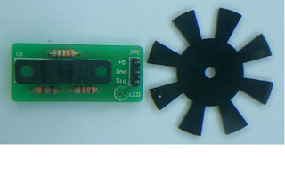
Photo above shows a example of a encoder
After calculate the speed of the stepper motor, the value of the speed should be displayed in LCD screen in the test board of the stepper motor.

Photo above shows a example of a LCD Screen

We combine all the client‘s requirement for the test board for stepper motor, the test board should have a pulse generator to generate the pulse, motor driver to drive the stepper motor, encoder to calculate the speed and LCD screen to display the speed of stepper motor.

Design Project Team 2009

Project Title : Test board for stepper motor
Project Team Name : Touch The Sky
Client : Mr. Tee Tze Wee
Lecturer : Mr. Liau Chung Fan

Project Team Members:
1. Goai Teck Liang (HK2006-3572)
2. Wong Jih Kian (HK2006-5159)
3. Siti Nor Nabilah (HK2006-2096)
4. Tamil Selvam (HK2006-4025)
5. Mohd Faizal (HK2006-6601)

My team: Non-Technical Roles
LEADER
– GOAI TECK LIANG
• Management (manages project, calling meetings, revise project plans, response to changing circumstances)

LAB COORDINATOR
– TAMIL SELVAM
• Coordinates lab work ( books lab, buys parts, prepares prototype)
PRESENTATION MASTER
– WONG JIH KIAN
• Presentation preparation ( PowerPoint slides, posters, brochures, CDs)
WEBMASTER
– MOHD FAIZAL
• Creating web-page, uploading information onto the webpage

SECRETARY
– SITI NOR NABILAH
• Document preparation, keeping track of teams accounts ( proposal, reports preparation & create a team accounts book)

Thursday, March 12, 2009

Stepper Motor Advantages


1. The rotation angle of the motor is proportional to the input pulse.
2. The motor has full torque at standstill (if the windings are energized).
3. Precise positioning and repeatability of movement since good stepper motors have an accuracy of 3 to 5% of a step and this error is non-cumulative from one step to the next.
4. Excellent response to starting/stopping/reversing.
5. Very reliable since there are no contact brushes in the motor. Therefore the life of the step motor is simply dependant on the life of the bearing.
6.The stepper motors response to digital input pulses provides open-loop control, making the motor simpler and less costly to control.
7. It is possible to achieve very low speed synchronous rotation with a load that is directly coupled to the shaft.
8. A wide range of rotational speeds can be realized as the speed is proportional to the frequency of the input pulses.