Testboard for stepper Motor

Showing posts with label project design. Show all posts

Sunday, May 3, 2009

Job distribution

Our project design is most of part in writing programming and hardware constructing. So we want to make sure every of our team members know how to write te programming. So we divide the job one part by one part to our team and give everybody a chance to learn the programming. Job distribution as shown below :

Wong Jih Kian : Speed control
Goai Teck Liang: Radio Frequency
Faizal: Motor Driver
Tamil : Encoder
Nabilah : LCD screen

After our team member knows how to write the programming for their own parts, we will combine everything together.

Things that we purchsed

Due to lack experience in microcontroller, and newbie in project design. Most of the devices we buy from shops rather to construst and build. We are mainly focusing on writing programming and learn how maximase to use those devices we buy.

Unipolar Steppr motor


Photo above shows a unipolar stepper motor that my team will use it. It is bought from cytron tecnology and cost us RM 50. We chose unipolar stepper motor for our project design because it is more easy to use it compare to bipolar stepper motor.

Motor Driver

Due to lack experience in designing the motor driver of stepper motor, we plan to buy this motor driver from cyton tecknolgy. We will discuss in details and advantages in future post. The motor driver cost us RM 135.

Encoder

Photo above shown an encoder. We are quite regret to buy this encoder. This is because we can easily build my our own. Furthermore, this encoder didnt provide the output shaft for us. So it make difficulty for us to construct a output shaft for it. It is very expensive , RM 60.

Radio Frequency (transmitters and receivers)


Photo above shows 2 set of different frequencies of radio frequency, 315 MHz and 415MHz. Due to we want to communicate in bi-directional between car and remote control that we already discussed in previous post. Therefore, 2 set of transmitters and receivers are needed.

Microcontroller (PIC 18 F 877A)
Photo above shows the 40 pin microcontroller that provided by the school. We need to learn it start from zero.

LCD display
Photo above shows the LCD display that we purchase from cytron. It is a cheaper LCD display. Again we need to learn how to write the programning for this LCD display. We will use this LCD screen to display the speed as well as the torque for stepper motor.

Saturday, May 2, 2009

Estimated budget for our product

Budgets are difficult but essential tools for project management. They permit teams to identify the financial and other resources required, and to match those requirements to the available resources. Budgets also require teams to account for project monies. Finally, budgets serve to formalize the support of the larger organization from which is drawn. Design project budgets normally include research expenses, materials for prototypes and support expenses related to the project. The table below is showing our estimated budgets:

Please click the photo to enlarge it
Estimated budget

Technical Gannt Chart for our team

To start any project, the technical gannt chart is very important to the team. It can push us to do for project and it is more systematically to the design. The photo below is shown the technical gannt chart designed by the Touch The Sky.

Please click the photo to enlarge it

Research method on our product

The development of the mass capacitive sensor involves research, step by step. The steps are affected by other factors, which cause some delay in certain cases. Each of the steps was planned well before proceed and sometimes interfere between each another occurred due to speed up the process especially in the cases where delay happened. Table 1 shows the overall flow of the project. The steps involved are elaborated briefly:
Please click the photo below to enlarge it

Table 1 : Flowchart of the project
Literature review and study are the ways for understanding of the title of the project. Research has been carried out on the papers, journals, books and Internet resources to create a strong background on the related topics involved in the project. The research conducted about the definition of stepper motor, microcontroller technology, stepper motor types (bipolar and unipolar specifically), motor performance characteristics, and the application of the stepper motor. This step also involved the complete understanding of the general view of the project’s scope.

Fast Diagram of our product

In the previous post, we already discuss the executive summary of our product. By seeing the fast diagram below, you will more understand about our product as well.


Please click the photo to enlarge it

Executive Summary of Our Project Design

Our product is Test Board for Stepper Motor. The main purpose of designing this product is for educational kit for a university student. However to make the learning process more interesting, we design the test board for the stepper motor in the form of car control. The main component of this product is stepper motor, PIC microcontroller, encoder and LCD (liquid crystal display). Moreover to control the car control we are using wireless remote by radio frequency.
The car is built with three wheels. For this product we only used one stepper motor and it only control one wheel of the car and the other two wheels is used to stabilize the car. It means that our car only can run forward and backward. Since our purpose of design this project is for educational kit, we ignore the car control problems to turn left or right.
In technically, we are design circuit by referring to the books, internet and also by our own idea. Then we are using Proteus 7 professional to design the complete circuit. Moreover to interface PIC with the stepper motor and LCD, we are using C programming. The complete program is simulated in the MPLAB IDE v8.10 and it is transfer to the PIC using PICkit V2.55 program.
There are many experiments we are doing in a process of building this product. We are dividing our product into several technical parts such as encoder, LCD, speed control, remote control and also radio frequency. Each of the part is experimented separately and any changing will be done due to the time.
The stepper motor will be control by a remote control using radio frequency. The input will be send directly to the microcontroller and microcontroller will send the data to the motor drive. Therefore the motor drive will drive the motor. The output of the motor will be send to the encoder to calculate the speed and from the encoder, the speed will display to the LCD to display the output.

Thursday, March 19, 2009

Objective of the project Design

OBJECTIVE
Design a test board for stepper motor. A product uses the test board should be designed. In addition, the product should be marketable and would appeal to the public.


Indented Objectives List
1. The product must be display the speed in the LCD screen
1.1 The product must be able to display the speed measured on a screen.
1.2 The product must be sensitive to small variations in speed of the user.
1.3 The speed sensors used must be reliable.


2. The product should be marketable
2.1 The product must be interesting
2.1.1 The product should be inexpensive to produce
2.2 The product must be attracting
2.2.1 The product should be suitable to all generation and worldwide.
2.3 The product must be convenient
2.3.1 The product must have simple structure
2.3.2 The product must be easy to operate
2.4 The product must be safe

2.4.1 The product must be well-insulated

Client Requirement From Our Project

In this project design, the client requires us to do a test board for the stepper motor. Inside the test board, microcontroller should be used to control the speed of the stepper motor. A microcontroller is a single integrated circuit with central processing unit (ranging from small and simple 4-bit processors to complex 32- or 64-bit processors). It contains the serial input/output such as serial ports (UARTs). It has the peripherals such as timers, event counters, PWM generators, and watchdog . In addition, microcontroller has volatile memory (RAM) for data storage and clock generator which often an oscillator for a quartz timing crystal, resonator or RC circuit . It includes analog-to-digital converters.. It requires in-circuit programming and debugging support.


Photo above shows a example of a microcontroller
In every stepper motor, it must have a pulse to generate the stepper motor. As a result the client requires us to build the pulse generator to the stepper motor. Pulse generators can either be internal circuits or pieces of electronic test equipment used to generate pulses.

Beside that, the client requires us to have a motor driver to drive the stepper motor. Stepper motor performance is strongly dependent on the drive circuit. Torque curves may be extended to greater speeds if the stator poles can be reversed more quickly, the limiting factor being the winding inductance. To overcome the inductance and switch the windings quickly, one must increase the drive voltage. This leads further to the necessity of limiting the current that these high voltages may otherwise induce.


Photo above shows a example of a stepper motor

Photo above shows a example of a motor driver of a stepper motor

Inside the test board, it must contain the encoder to calculate the speed of stepper motor and display it at LCD display. An encoder is a device used to change a signal (such as a bitstream) or data into a code. The code may serve any of a number of purposes such as compressing information for transmission or storage, encrypting or adding redundancies to the input code, or translating from one code to another. This is usually done by means of a programmed algorithm, especially if any part is digital, while most analog encoding is done with analog circuitry.
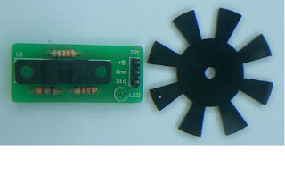
Photo above shows a example of a encoder
After calculate the speed of the stepper motor, the value of the speed should be displayed in LCD screen in the test board of the stepper motor.

Photo above shows a example of a LCD Screen

We combine all the client‘s requirement for the test board for stepper motor, the test board should have a pulse generator to generate the pulse, motor driver to drive the stepper motor, encoder to calculate the speed and LCD screen to display the speed of stepper motor.